e stop wiring diagram
Emergency stop wiring diagram edge schematic button circuit rit edu switch control motor potential solution cutting power rh. Typical Wiring Diagrams For Push Button Control Stations Start-Stop Control Wiring Diagrams 4 SINGLE STATION - MAINTAINED CONTACT PUSH BUTTONS t-----t L1 UNDERVOLTAGE.

Circuit Diagrams Of Safety Components Technical Guide Australia Omron Ia
E stop wiring Alarm 24 circuit breaker FRSF drive.
. I have a few existing generator installations where I need to install a new remote E-Stop switch. It is still not allowed to energise a supply with this type of device. Read customer reviews find best sellers.
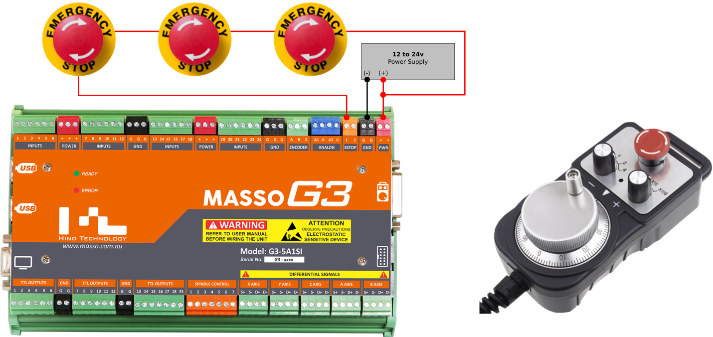
K1 NO1 PB3 PB4 PB5 should be of potential free contact. 18 Pictures about Wiring for AutoStartStop - help with wiring the blocks O Gauge. Current Solution If you are referring to the physical E-Stop switch as opposed to one in software such as in Mach3 then all you really need to do is connect it to the power leg of your machine.
A few are Kohler 40kw units with existing E-Stops. Schemes Diagrams Wiring Diagram Online E Stop. Full stop If you are employed then the onus is on your.
Alarm 24 circuit breaker FRSF drive Wiring safety switch and e stop button to r30ib plus. The E-STOP you describe. Like rafahil said the hold signal is not a safety signal and although the.
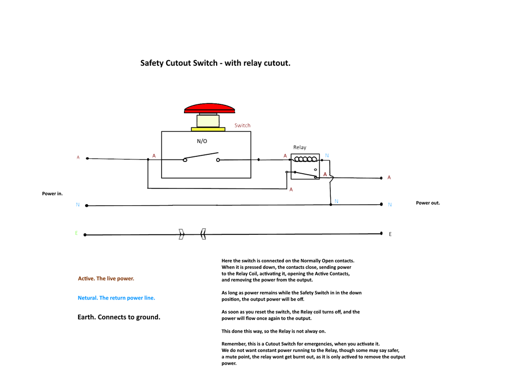
The design of the emergency stop stop category 0 consists of an emergency stop button as an activating switch a safety relay as a logic unit and a contactor as an actuator for bringing the. In this episode we will learn how emergency push buttons are wired the correct way. It requires a NC Normally connected circuit for the machine to.
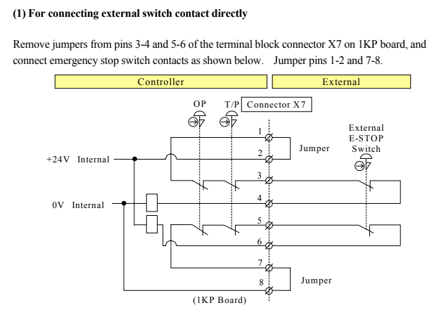
18 Pictures about How To Install a 3-way Switch Option 1 - The Home Improvement Web Directory. Connect or do wiring as per vfd side drawing you take 24 V from the VFD PCB directly. Emergency Stop Switches Type ES Knock out for plastic version IMPORTANT NOTE.
And why not the other wayConsider support via donation from the link u. Power to motor live 24. The machine is rated for 20A on the mains label.
You need to wire it as shown in the diagram. This is the industry standard. Acrossland Inc R80 Series - E-Stop Switch With LED.
This part presents basic examples in which a G9SA Safety Relay Unit G9SX Flexible Safety Unit F3SX Safety Controller and F3SP-B1P Safety Light Curtain Controller. Here is a printable template to help you plan for your E-Stopp installation. Estop Wiring Model.
Using PLC outputs is not acceptable if not a safety PLC. Wiring diagram for power supplies l n l n l n switch mode psus and toroidal E stop wiring. Jan 6 2012.
Using a contactor with emergency stop. E Stop Wiring It can be operated manually and must remain in its open position until the normal operation can be restored. Just download both halves print them on a standard printer tape them together and youre all set to ensure your E.
I would recommend wiring the E-Stop to an input terminal via an NC connection. Each leg is pulling 9A under max load though and the contactors on the back of the estop is. All Emergency Stop Switches conform to European Sta E-Stop Button.
Plc electrical panel wiring diagrams diagram schematic basic circuit examples stop engineering power functions hardwired critical devices including safety should. 9 Images about Alarm 24 circuit breaker FRSF drive. A twist to release e-stop is a normal e-stop.
Vfd start stop wiring diagram. How To Install a 3-way Switch Option 1 - The Home Improvement Web Directory. Ad Browse discover thousands of brands.
The single wire safety output l11 and the auxiliary output y32 are off. Wiring for AutoStartStop - help with wiring the blocks O Gauge.
Emergency Stop Button 10 Steps With Pictures Instructables
Emergency Stop Switch Wiring
Kawasaki Emergency Stop Wiring Technical Questions Robotexchange

Three Phase Motor Control Circuit Emergency Stop Youtube
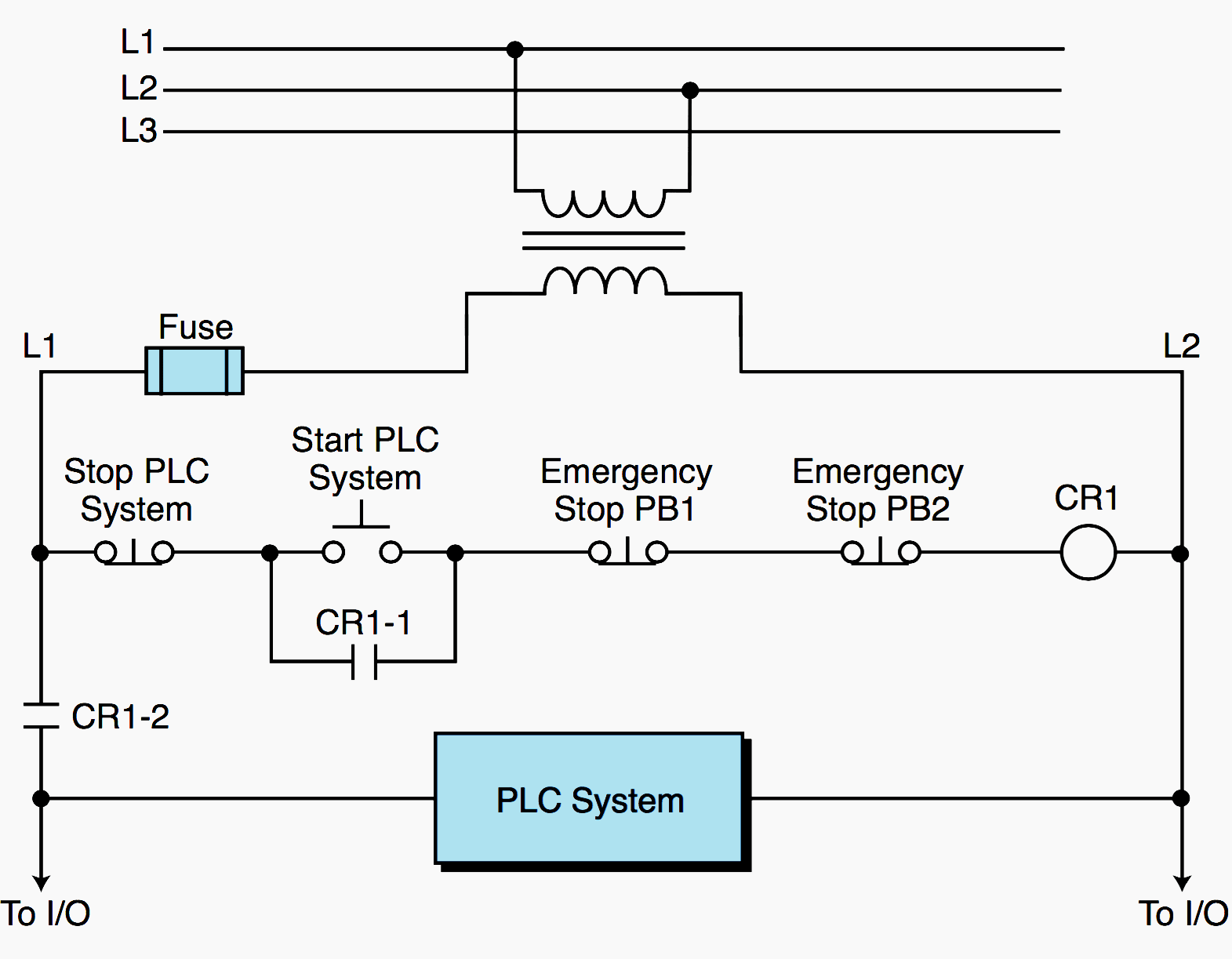
Plc Power Supply And Safety Emergency Circuits Requirements Eep

Diagram 3 Phase Emergency Stop Wiring Diagram Full Home Electrical Wiring Electrical Circuit Diagram Circuit Diagram

Wiring Safety Switch And E Stop Button To R30ib Plus Controller R Fanuc

Emergency Stop Switch Crowley Marine

Mpcnc Emergency Stop Feed Hold Resume Pendant The Smell Of Molten Projects In The Morning

Machine Wiring Circuit Madvac Cnc
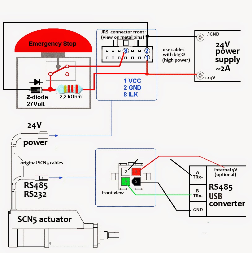
Tutorial Scn5 Wiring Tutorial

Wiring Diagram Assistance
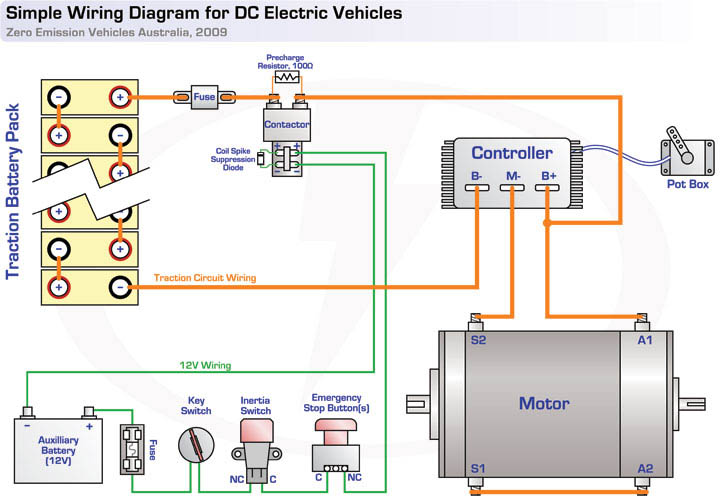
Ev Tech Info Circuit Diagrams

Diagram Of Supply And Emergency Stop Of The Installation Download Scientific Diagram

Circuit Diagrams Of Safety Components Technical Guide Australia Omron Ia

Emergency Stop Button 10 Steps With Pictures Instructables

Circuit Diagrams Of Safety Components Technical Guide Australia Omron Ia